Load Cell Fault Finding – Part 2

dbbw-200x200

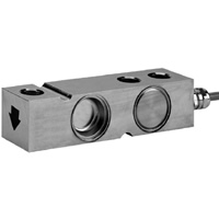
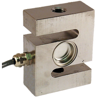
‘S’ Beam Load Cell

We often get asked for fault finding tips and so I’ve put together a simple fault finding guide for a load cell system.

In the previous blog we discussed the load cell part of the system, in this post we discuss the signal conditioning part of the system and provide a summary….

Check signal conditioner excitation voltage

If we measure the excitation voltage without the load cell connected we can check that it is the correct value for our load cell. A lower excitation voltage will give a smaller full scale reading but should still work correctly. A higher excitation voltage could cause the load cell to overheat and alter its characteristics. (If we then measure the excitation with the load cell connected this could show up other potential issues).

Check there aren’t too many load cells connected

We should also ensure that there are not too many load cells connected. Check the total resistance of the load cells either by calculation or measuring with a multimeter. Four 350 Ω load cells in parallel will drop the resistance to about 85 Ω. Check the specification on your signal conditioner to see what the minimum load is.

Short between signal inputs to signal conditioner to simulate zero load

webala5x

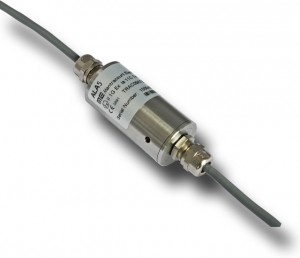
Mantracourt’s Signal Conditioner ‘ALA5’

The next check on the list is to short between the inputs on the signal conditioner. This will simulate a load of zero and should give a zero output (with gain and offset set to one and zero respectively).

Ensure that shunt cal is not active

Some signal conditioners have a shunt cal function. This shunts the output by a fixed value to check the integrity of the load cell, wiring and signal conditioner. If there is any deviation from the last time shunt cal was performed then further investigation is required. If shunt cal is left on then it will completely mess up any real readings. Please note that the shunt cal should never be applied without the load cell connected.

Check six wire or four wire load cell and signal conditioner

If you have a 6-wire signal conditioner with a 4-wire load cell it is important that you link the sense and excitation terminals at the signal conditioner. Otherwise there will be no sense input and therefore no reference point for the signal conditioner. (If you have a 6-wire load cell with a 4-wire signal conditioner it is worth linking the sense and excitation as this will reduce the overall wire resistance).

Check correct power supply to signal conditioner

Check the output from the signal conditioner is what the display needs as its input. Some signal conditioners can output several different protocols which need to be set up correctly.
IMG_6398

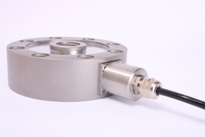
‘Pancake’ Load Cell

Ensure polarity is as required

Check that the positive direction of the load cell corresponds with the positive reading required.

Check gain and offset correctly set

Ensure that gain and offset are set correctly. It may be necessary to try recalibrating at this point if necessary, see the relevant manual. Depending on your setup this could be an absolute nightmare so should be held as a last resort.

The output cabling checks are very similar to the load cell cabling but will be marginally less prone to noise.

Most of the topics that I have covered here are very complex and I have barely scraped the surface. I’ve only very briefly touched on the output and display sections of the system which will be discussed in future blogs.

In Summary:

Check correct output type from signal

Check the signal conditioner has the correct power supply. See the relevant manual.

Load cell

  1. Check correct wiring connections and colour coding
  2. Check load cell resistance between excitation +/-
  3. Check load cell resistance between signal +/-
  4. Check for mechanical restriction on load cell movement
  5. Check to see if load cell has been overloaded

Cabling

  1. Keep distance between load cell and signal conditioner to a minimum
  2. Keep all sensor cable runs away from inductive loads
  3. Ensure that you are using twisted pair, screened cable
  4. Check cable is screened and only connected to ground at one point
  5. Test cable continuity

Signal conditioner

  1. Check signal conditioner excitation voltage
  2. Check there aren’t too many load cells connected
  3. Short between inputs to signal conditioner to simulate zero load
  4. Ensure that shunt cal is not active
  5. Check six wire or four wire load cell and signal conditioner
  6. Check correct power supply to signal conditioner
  7. Check correct output type from signal conditioner to display
  8. Ensure polarity is as required
  9. Check gain and offset correctly set


Hopefully this has given a helpful starting point for fault finding load cell systems.

For more detailed advice and support please contact us at mantracourt.com

By Tom Lilly, Technical Support Operator at Mantracourt

Load Cell Fault Finding – Part 1

We often get asked for fault finding tips and so I’ve put together a simple fault finding guide for a load cell system.

The output from a load cell is tiny! Any small interference will show up and then be amplified by the signal conditioner. The longer the cable the greater the interference will be due to increased coupling.  It will be improved if screened, twisted pair cable is used as with a good quality signal conditioner this will allow a lot of noise to be removed.

A certain amount of physical noise is normal, especially in very sensitive load cells. This can be from all sorts of sources ranging from computer fans on the same desk as the load cell to fork lift trucks driving around on the floor above! The more sensitive your equipment, the greater the degree of separation that is required from the rest of the world!

In figure 1 below, we can see a diagram of a load cell system.

Fig1

Figure 1.  A load cell system

For this guide I have decided to split the fault finding into the areas load cell, signal conditioner and cabling.

I’ll start with the load cell…

Check correct wiring connections and colour coding

The first thing that I’d check is the wiring connections between the load cell and the signal conditioner. The colour codes vary between manufacturer and it is best not to assume anything. Usually the colour coding is on the load cell’s calibration certificate. Ensure that the wiring is as described. Getting this wrong can give inverted or biased results.

Check load cell resistance between excitation +/- and signal +/-

Also on the calibration cert should be the resistance between excitation +/- and also between the signal +/-. Measure those resistances with a multimeter to confirm that there is no internal damage to the sensor. (There will be a little variation from the figures stated on the calibration and this is normal). Don’t forget to disconnect the load cell from the signal conditioner before doing this.

Check for mechanical restriction on load cell movement

Have a good look at the load cell. Is it free to move? Any mechanical restriction will have an effect on the load cell’s output. (You can also use this phenomenon to limit the total movement of the loadcell to prevent accidental overload). Even poor cable routing can twist a small load cell and give skewed readings. Therefore it is important to make sure that the cable routing is free from any strain. Also the weighing vessel needs to be free to move in the direction of the load.

Check to see if load cell has been overloadedosbst-200x200

Another possible problem is if the load cell has been overloaded. A small load cell could have been overloaded simply by leaning on it. If this has happened it may have permanently deformed the load cell and it will not return to its zero position correctly. This is likely to show as a non-zero reading under no load. There is a high chance that this will be terminal! Talk to your load cell manufacturer for more information.

Now we can look at the load cell cabling. As previously mentioned, the voltage outputs from the load cell are very small and easily influenced by the outside environment. There are several ways of minimising the disruption.

Keep distance between load cell and signal conditioner to a minimum

The further apart the load cell and signal conditioner are, the more susceptible the cabling is to capacitive coupling and electromagnetic fields. Keep this cable short and there will be less interference.

Keep all sensor cable runs away from inductive loads

It is very good practice to ensure that all sensor related cables including sensor power are kept separate from any inductive loads and their power feeds.

Ensure that you are using twisted pair, screened cable

Using twisted pair cable can help reduce the magnetic influence of power cables. This needs to be in partnership with a signal conditioner’s common mode rejection capability. Screened cable prevents capacitive coupling by coupling to ground instead of the signal wires.

Check cable is screened and only connected to ground at one point

If the screen is grounded at more than one point a ground loop is created. This is the cause of the earth hum in audio systems. This is just as problematic in instrumentation systems. Remove any extra link(s) between screen and earth. DO NOT disconnect the earth wire of the appliance in question. This is dangerous and can cause serious injury.

Test cable continuity

A simple continuity test can check the integrity of the cabling. Disconnect the cable and check the resistance.
In the next post we will discuss the signal conditioning part of the system….

By Tom Lilly, Technical Support Operator at Mantracourt
Continue to Load Cell Fault Finding – Part 2

A Marketing Intern’s Perspective

My name is Konstantin Delov and I’ve been part of the Mantracourt Marketing team for almost half a year now. I spent my summer working on improving our online presence and supporting our network of technical partners in the promotion of our products. I was fortunate enough to be around and participate in the preparation of two of our product launches – both T24 and BroadWeigh Updated Range.

In the next few lines, I’d like to reveal a unique side of Mantracourt that very few people can see, along with a short story on my participation at an international innovation competition.

Behind every great achievement stand a number of strong supporters. People’s attention is often focused on the final result, but that doesn’t diminish the importance of the bits that quietly, but consistently contribute to it. Just like our signal interface solutions that support a variety of industries, often remaining unnoticed.

A few months ago, I heard that same monotonous buzz indicating an incoming email. Though the content of the message was a bit more special than usual. I was being notified by Microsoft corporation that me and my Exeter University team had reached the World Wide finals of the biggest student competition there is – The Microsoft Imagine Cup. I was going to visit their HQ in Redmond, Seattle, play with HoloLens and pitch to some of the most influential figures in the corporation.

11813263_10101728359496125_2891213987418652811_n

Sounds exciting, but it’s not the type of trip that you just go to. It tested our limits as a team and individuals, required us to burn the midnight oil on a frequent basis. It involved thorough planning and outstanding discipline. Selling an idea is not among the easiest of things.

Fortunately, the work paid off and my team became third worldwide in the innovation category!

PastedGraphic-1

And yes, it might have been me filling out the quotes for the press releases and smiling for the photos but, once again, without the skills that I had gained at Mantracourt things could have looked way different. The company taught me consistency. I managed to get a close look of how an organisation with worldwide distribution gets its message across and reaches its sales targets. You can’t simply learn these lessons in a lecture theatre.

In this day and age, Mantracourt is a rare example of a company that doesn’t just blindly follow numbers. It is a place where every employee, customer, supplier or contractor is respected as a valuable part of a team, rather than a production or sales robot. And this pays off. Every piece of electronics that comes out of our factory is manufactured and tested by people who want to see the company thrive. Every board that we sell is sought and needed by the customer. We always make sure that it will genuinely help them towards achieving their goal, be it for project or distribution purposes.

By Konstantin Delov, Marketing Intern at Mantracourt

Why Go Wireless?

There are many good reasons to switch to wireless for your sensor requirements. It almost seems an easier question to ask ‘why not?’ but I’ll start with ‘why?’

The Benefits…

The first, most obvious plus for wireless is the lack of wires!  With moving loads, trying to keep the cables neat, tidy and unbroken can be a pain. Depending on the installation, replacing damaged cables can be very tricky, time consuming and expensive. Fault finding on complex systems can also be very time consuming.

With a wireless system the initial installation process can be very quick and easy. Wireless sensors can be moved to different places if continuous monitoring is not required, saving costs.

All our transmitter modules can run on batteries, also removing the need for power cabling. Depending on sample time and frequency battery life of up to 5 years is achievable.

Devices can be easily swapped out if required. It is even possible to change the data tag of the new device to match the one being removed so none of the receivers need to be changed.

Extra devices can be easily added to the system. Only requiring simple reconfiguration of receiver devices.

Wireless Issues and How We Address Them

People often worry about the security of their data. When sending data wirelessly anyone with the correct receiver could also be picking up all the data. Fortunately we have a way around this with Group Keys. Once a Group Key is set, only devices using the same Group Key can ‘see’ the data from that device. (The Group Key offers millions of different combinations).

Another concern can be about interference from other devices. Firstly, due to the T24 error checking, if data is being displayed, it will be the correct data. There is a possibility that other radio traffic could interfere with T24 transmissions and we therefore provide within our Toolkit a spectrum analyser to check radio traffic on the 2.4GHz frequency band. If heavy traffic is discovered simply switch to a less congested channel.

Before installing any system it is important to test that it is correct for your uses. Our T24 Toolkit allows for monitoring of radio signal levels at both the device and the base station to allow full analysis of variation with movement and other environmental factors.

For our testing we use an open field site with the transmitter 3 m above ground and the receiver at 1.5 m above ground. Increasing either height will generally increase the range. Any obstacles within range will affect how the radio propagates and will change the range and coverage.

It is also worth noting that the positioning of the components that make up any wireless telemetry system always involves a degree of experimentation.  Time spent on this aspect will always ensure a successful outcome.

By Tom Lilly, Technical Support Operator at Mantracourt
Tom’s Tech Tips

The T24 data logging software and data mapping software is now available to download free of charge.  Tom Lilly, Technical Support Operator at Mantracourt, talks us through this intuitive application…

The full functionality of T24LOG100 is now available to anyone that wants it at no cost. It means that people can have a proper experiment with an important part of a system without any expenditure. This should allow people to discover how useful and easy the T24 system is. You don’t even need a base station to have a look through and change the sample projects. The tooltip help and main help files are really useful for getting to know the software.

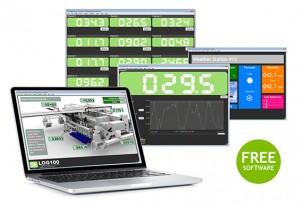
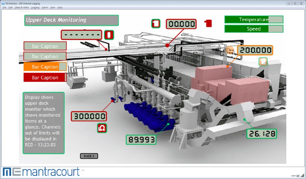
T24LOG100_Montage-webAll the functionality is there.  We have up to 100 channels of display and data logging, trend charts, mapping functions allowing intuitive visual displays, report generation and web server function for viewing on multiple platforms all over the world!

What do we mean by 100 channels?  Well, these channels can either be T24 transmitter modules or mathematical functions based on the transmitters and/or other display channels. Each channel has the option of setting a peak or valley hold or varying filtration levels. All display channels can also have warning, underload and overload levels set.

All the display channels can be logged to a csv file. This can be triggered manually or automatically at intervals and opened in spreadsheet software such as MS Excel.

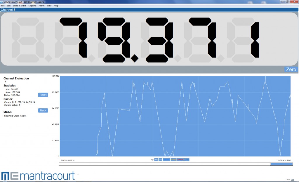
Double clicking on any of the display channels shows detail about that channel including a trend chart with up to 10,000 data points.

The mapping function gives the possibility of creating intuitive displays needing very little explanation. Image files such as JPEG, PDF and DXF can be imported and other objects such as status icons, level indicators and displays can be placed on the page. With some clever thought, items can T24LOG100_Web_Server-webbe made opaque at certain levels and clear at others allowing the images to change as the load state changes. Up to eight pages of display mapping can be used. As previously mentioned, the example project has some useful demonstrations.

Reports can be generated and saved or printed when required. These can be in various pre saved formats.

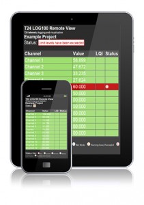
Finally, my personal favourite is the web server. With this we can see a simplified version of the main display page in a web browser. This then means that if we know the IP address and password we can view this info on any computer, tablet or smartphone connected to the same network as the host computer. It is also possible that we can dial in from anywhere in the world to see the displayed data.

As well as the demo projects with the data logging software we now also have the first in a series of demonstration videos on LOG100. This can be found on the Mantracourt YouTube channel – click here to view.

By Tom Lilly, Technical Support Operator at Mantracourt

T24_Wireless_Telemetry_FrontCover-Nov14-PlaySymbol

Meet the Team – Manufacturing Team Leader

Tracey Richards, Team Leader of Mantracourt Manufacturing talks about how quality is integral to her role and how her electronics career has taken her from photocopiers, to military equipment, to industrial instrumentation.

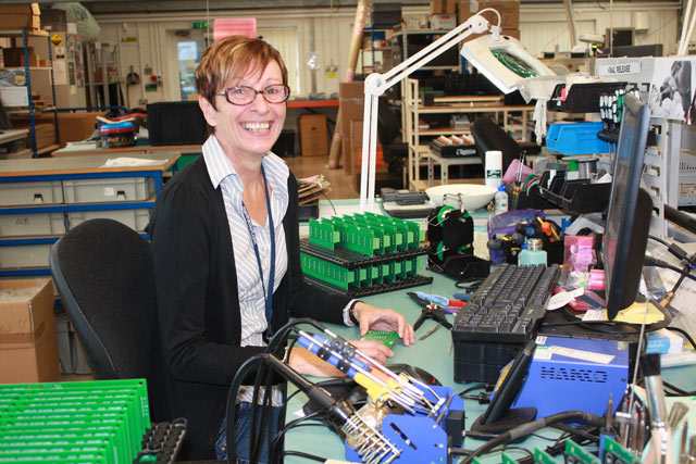
I will start off by telling you all a bit about myself. I have been at Mantracourt since 2011. When I started, my role was to be the team leader for our standard product line of instrumentation and I am now the team leader of the Mantracourt manufacturing team. There are 12 people in our team.

I am responsible for the quality of products leaving Mantracourt.  Also, sub-assemblies we receive from our suppliers, training, day to day running of the department, manufacturing instructions, equipment and new procedures and techniques that become available.

Most of my working life has been in the Electronics Industry. My first job was at Rank Xerox, Welwyn Garden City. Although I was to be working in manufacturing, I had a two week training period. It was spent in a training room and we were not allowed to touch any product during this time. In truth it was a good job too. The programme for us was to learn how to identify components, resistor colour codes, component values, rework, track and pad repair, which has always come in handy and modifying PCBs. When leaving Rank Xerox, I went to work for Hocking Electronics NDT. Here I learnt how to wire wind probes and work to MOD standards. As I continued my working career I always went somewhere where I would improve my skills and knowledge. I can work to IPC-A-610 Class 3. My experience comes mainly from working in the Military, Medical and Aerospace industry.

The training of team members at Mantracourt is of the highest standard and we work to IPC standards Class 2.  I undertake all training to staff on an ongoing basis as and when new techniques change.

I encourage the team to learn from each other.  We regularly talk about processes and lessons learned and ideas for regular reviews.

We operate a Quality Management System where all equipment has to be documented and records of calibration and any testing that has taken place is stored. Drawings, tests, rework, are all recorded.

We have regular internal audits, which includes ESD (Electrostatic Discharge) checks to benches and floors, which are checked monthly.  A personal ESD check, which includes correct footwear and the use of wrist straps, are done on a daily basis.  I make sure everyone is working within a safe environment.

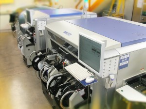
At the end of the SMT (Surface Mount Technology) line we have an AOI (Automatic Optical Inspection) machine that most of our products go through.

This inspects the boards for misplaced components, dry joints, correct orientation and correct component ID.

We also carry out visual inspection on all products to check the final quality before shipping.   We take quality very seriously and as a team leader, maintaining quality is my most important job.
We are ISO9001 certified and manufacture ATEX approved and RoHS compliant products.

Here are some interesting statistics. The team and I are very proud of what we achieve.

  • Our production yield is 99.96%
  • First time pass rate over total operations 98% (where a single product may include 10 or more operations)
  • Scrapped 0.04%
  • Product returns due to manufacturing issues – quantity 5

2012 / 2013 statistics”

Manufacturing is a precise business and I am very proud to work with such a great team that help to produce the high quality products that we are renowned for.  For me personally, and this is what I ask my team to keep in mind – if you were going to buy one of our products with your own money, would you buy it?
Even though I don’t deal directly with our customers their requirements are first and foremost.

On a closing note, one of my team members overheard a conversation I was having with Rebecca in the sales department. At which point he said to me I had made two statements, one of which was impossible and the other which was totally true. The first statement was, “Just ignore me Rebecca” he said that’s impossible to do. The second statement was “I don’t know Rebecca” he said now that’s true.   I suppose I can’t always be right…well not all of the time!

By Tracey Richards, Team Leader at Mantracourt

Did You Know About The Handy Battery Life Calculator?

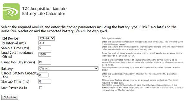
Always keen to provide helpful tools to assist you, our design engineers have produced a clever tool to predict how long the batteries will last in the acquisition module of your T24 wireless telemetry system – the Battery Life Calculator

By simply selecting the required module and inputting your chosen variables into the calculator, you will be able to obtain a prediction of the expected battery life.

Click to open the Battery Life Calculator

By Dave Porter, Technical Sales at Mantracourt
technical@mantracourt.com

Manufacturing Talent

My name is Fabian and I am twenty years of age.  I started working at Mantracourt Electronics in November 2013 as an Electronic Manufacturing apprentice.

When the opportunity came along to start an apprenticeship at Mantracourt I jumped at the chance.  I have always been interested in technology and had worked on my own projects in my spare time, including fixing resisters and capacitors on iphones, PC’s and gaming consoles.  To have the opportunity to do something that interests me where I could work and train at the same time with good job prospects was a dream come true.

When I first started, one of my first tasks was to learn the basics of soldering different types of retrofit components and surface mounts components.  Although a little daunting at first, this was a skill that I picked up very quickly.  I also learnt how to rework circuitry; this is a particularly useful skill for moving components, if needed.

I started practising on scrap boards until my team leader decided that I was competent enough to work on products.  This was really exciting because when a board that I soldered passed test for the first time, my team leader was very impressed and I felt proud of myself.

I was also taught about the effects of Electrostatic Discharge (ESD) and how to prevent it in the workplace.

A month later I was learning a lot of new skills, such as how to use the EBSO machine (selective soldering machine).  This was a great privilege because only certain people are trained on this and it felt great to have importance and responsibility in a job.

I attend college once a week and am studying maths and science.  I also learn about how to work with machines and different types of tools in the workshop.  The workshop lesson is my favourite aspect because I am learning skills that are really useful at Mantracourt and compliment the in-house training that I receive.

The best thing about working at Mantracourt is the fact that I am learning new skills and I have finally discovered something that I’m good at and enjoy, and the bonus is I get paid for doing it!

It is also so rewarding to see the end results of a product that I have spent time on, finished and working and ready to go off to our customers.

As an apprentice I will get the opportunity to work in all aspects of the business, including  sales, marketing and with the design engineers.  There is a great team of people here.

As part of the in-house training and education I have worked with various products from our standard product range.  An example is the SGA/D, which is a high performance signal conditioner, for use with strain gauges.  It offers a wide bandwidth and a wide input signal range.

Let me explain the processes this item goes through in basic terms…

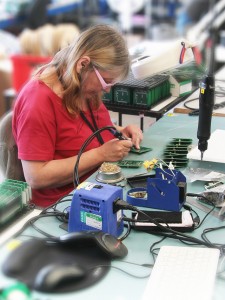
This product starts by going through the SMT Line (surface mount machine), this puts all the surface mount components in their correct places.

The next step is a high speed visual inspection by a machine that checks that each component is correctly located, checks for the integrity of the solder joints and can also identify if any component has an incorrect value.

Once this is done it is moved over to the EBSO machine.  This is where all the retrofit components are put into place and soldered with a small ‘wave’ of solder.  The correct nitrogen levels are essential.  We put four of these boards through on each run, and each run takes about 12 minutes.

For every operation that is undertaken on the product you must mark off on the Product Database which stage it is at and how many products have been through this stage.  This means that once the boards have been through the SMT line they must be marked off and inspected.

After the boards have been through all of the assembly processes it’s time for them to get tested.

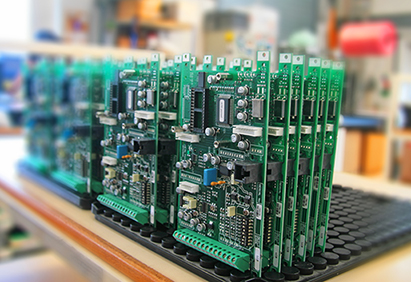
All products undergo rigorous quality testing and we have different methods of doing this, but they mainly undergo testing by the automatic test equipment system (ATE) using various jigs.

Once the SGA’s have passed the ATE test they are then put into their respective cases and are transferred to the dispatch department, where they are put into stock, or packaged and sent off to our customers.

I think the biggest challenge for me so far has been learning all of the different component names and learning where each component is stored.  This took some time but now I am familiar with these…it’s just like riding a bike!

My goals for the future are to learn how the entire organisation works, and to have first-hand experience of every aspect of the company.  I would love to get involved with product design and create my own product for the company one day…. watch this space!!!

By Fabian Gilson, Electronic Manufacturing Apprentice at Mantracourt

Highlights of the T24 Logging Software

I have had a lot of enquiries recently asking about our T24LOG100 software and how it can work for them, so thought this a good opportunity to discuss the main aspects of this incredibly smart piece of monitoring technology developed in-house by Matt Nicholas our IT and Software Guru.

The latest version of our T24LOG100 instrumentation monitoring software includes advanced features such as a graphical / mapping capability and a facility for remote viewing via a web server.

Mapping

A variety of image formats including PDF, JPEG and DXF can be imported to incorporate into your project. This innovative application facilitates a real-time monitoring system with simultaneous displays of load cell data presented as graphics on a visual representation of the structure on which the sensors are located.

This display features “drag and drop” placement of customizable readouts, warnings and user definable “buttons” to toggle between pages, reset alarms etc.  The use of a graphics background for the application offers a system which has the advantage of allowing a more intuitive and accurate response to the management of multiple and interacting loads.

Up to eight pages can be defined and you can switch between pages. Clicking displayed values, which can be in the form of digital display or bars, takes you back to the ‘zoomed in’ view so you can quickly investigate values.

Web Server

The T24LOG100 software now has a built in web server to provide a summary view page to other computers, tablets, iPads and smartphones etc using a standard browser. This summary page shows all channels and error and alarm status.

The new web server facility enables users to view the data online wherever they have access to their network. Users now have the freedom to monitor sensors and installations when on the move and on-site.

The built in web server also allows you to add your own custom web pages.

T24LOG100

T24LOG100 software is a data logging package that can handle up to 100 channels of wireless instrumentation data simultaneously whilst also offering a range of sophisticated features that will enable users to optimise system monitoring.

You can ‘zoom in’ on individual display channels to view detailed information on that channel along with 10,000 points of historic data.

The T24LOG100 display is customisable and it can be branded with company colours and logo and licenced for distribution.

Certain versions also come with the option of royalty free distribution to your customers.

If you have any questions please do not hesitate to contact me.

By Dave Porter, Technical Sales at Mantracourt
technical@mantracourt.com
Tel: +44 (0)1395 232020

The Sky’s the Limit – Highlights from the Past Four Decades at Mantracourt Electronics

2014 marks the 40th anniversary for Mantracourt Electronics and throughout this year we will be delving into the archives to share with you some of the highlights from the past four decades.

From our humble beginnings, which started life in a garden shed to the 3,600 sq ft manufacturing facilities we now occupy, we have supplied measurement instrumentation to some very well known and innovative projects.

One such project came along in 1985 and involved NASA’s Space Shuttle Programme.  A temperature and humidity monitor supplied to Solomat, another East Devon company at the time, was supplied to Honeywell and used in a satellite which was carried by the space shuttle.

The story is captured in the article below and tells the tale of our beginnings and of the project.

“Into Space from East Devon” – Wednesday, 31 July, 1985 (Source: Express & Echo)

We hope to post some more articles and photos from our archives during this anniversary year to entertain and inspire! Follow us on FacebookTwitter and LinkedIn.